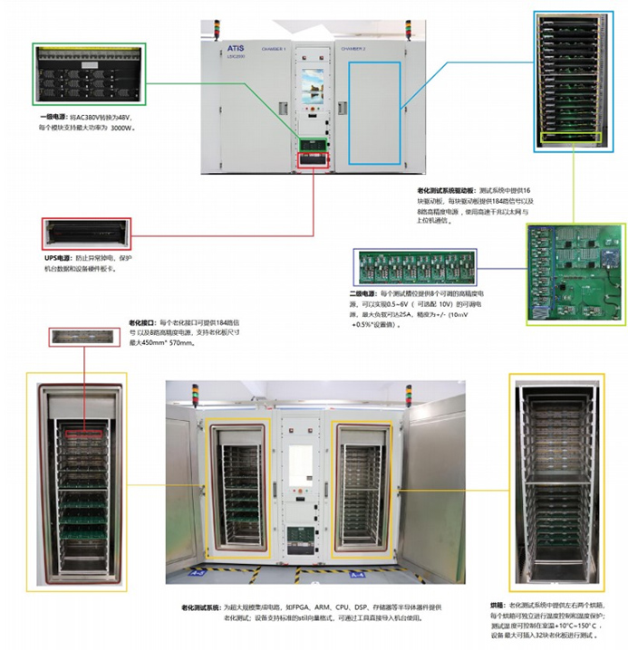
LSIC Burn-in Test System for Semiconductor Devices
The LSIC burn-in test system is designed for evaluating the burn-in performance of semiconductor chips. Semiconductor chips may experience burn-in phenomena after prolonged operation, such as decreased capacitance and increased leakage current. These phenomena can affect the performance and reliability of the chips. Therefore, the LSIC burn-in test system is used to simulate the environment of long-term chip operation, allowing for the testing of chip performance and reliability after extended use.
This system typically includes various testing conditions such as heating, cooling, and constant temperature control. It is equipped with specialized measuring instruments to assess the chip's electrical, thermal, and mechanical properties. Additionally, the test system can record parameters such as usage time, voltage, and temperature, aiding engineers in analyzing chip performance and predicting its operational lifespan.
| LSIC2000/7000 Series | LSIC8000 Series |
| 1. Provides 32 burn-in slots, capable of independently burn-in 16 different devices. | 1. Provides 16 burn-in slots, capable of independently burn-in 16 different devices. |
| 2. Each burn-in slot offers 184 programmable digital signals, including 32 bidirectional I/O. | 2. Each burn-in slot offers 128 programmable digital signals, all 128 are bidirectional I/O. |
| 3. Each burn-in slot provides 8 DPS secondary power supplies, with voltage ranging from 0.5 to 6V, current from 0 to 25A. The voltage accuracy of the power supply is within ±5% + 30mV, and the current accuracy is within -1% + 50mA. | 3. Each burn-in slot provides 8 DPS secondary power supplies, with voltage ranging from 0.5 to 6V, current from 0 to 25A. The voltage accuracy of the power supply is within ±5%o + 30mV, and the current accuracy is within +1% + 50mA. |
| 4. Rise/fall time is 10nS. | 4. Rise/fall time is 10nS. |
| 5. Maximum driving current for digital signal pins: 50mA. | 5. Maximum driving current for digital signal pins: 50mA. |
| 6. Maximum frequency for digital signals: 12.5MHz. | 6. Maximum frequency for digital signals: 12.5MHz. |
| 7. Maximum vector depth reaches 16M. | 7. Maximum vector depth reaches 16M. |
| 8. File format is VEC, supports direct conversion from STI1 format to VEC format. | 8. File format is VEC, supports direct conversion from STI1 format to VEC format. |
| Supports vector instructions ADV, HALT, SFX, CRFX, LIX, MSSA; jump instructions: JUMP, RPT, JIX, JNIX, JFX, JNME; call instructions: CALL, RET. | 9. Supports vector instructions ADV, HALT, SFX, CRFX, LIX, MSSA; jump instructions: JUMP, RPT, JIX, JNIX, JFX, JNME; call instructions: CALL, RET. |
| 10. Supports 8 independent temperature controls, with temperature control accuracy up to 3°C. |